
Planning the System
Induction Loop system design and installation is simple, provided a few basic facts are understood. To avoid poor performance and the need to re-position the amplifier or loop cable at a later stage, please select the appropriate amplifier and cable to suit the coverage area required. However, it is important to consider the construction of the building and the potential effect of any other equipment in the room or in neighbouring rooms. If in doubt, please contact us for advice.
Area of Coverage
The maximum square room coverage (with ideal conditions) is usually specified by the manufacturer. For rectangular (2:1) aspect ratio coverage this value may be increased by around 20%. For example: an amplifier which has a square room coverage of 200m² will cover a rectangular space with 2:1 aspect ratio of around 240m².
Sometimes, the system may not have to cover the whole of a room. For example, churches may only require coverage in the pews. Seek advice from the relevant authorities before installation begins.
Loop Cable Selection
There is nothing special about induction loop cable. Almost any single core tri-rated cable can be used for the induction loop provided it is of the appropriate DC resistance (ideally 0.5 to 1 Ohm). For a neat installation during a complete refurb or new build project, flat copper tape can be installed on the floor before floorcoverings are laid.
The graph shows the recommended CSA for different lengths of loop cable. Simply calculate the length of the loop required and choose a cable size that falls into the non-shaded area of the graph.
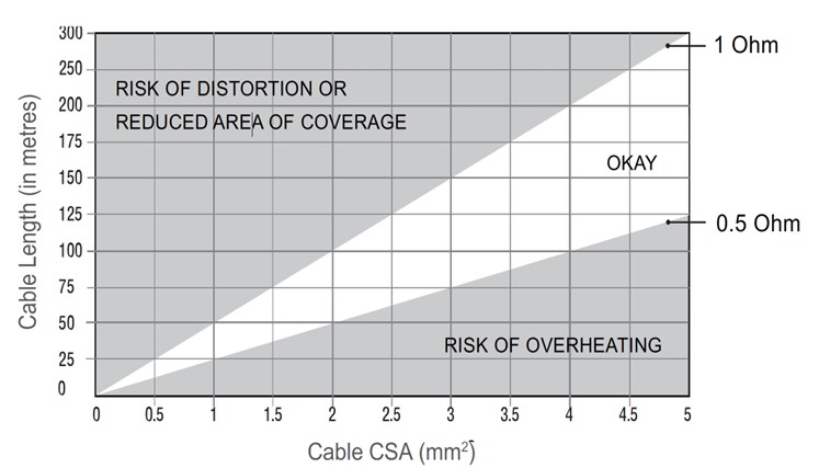
For example, to cover a room 15m x 10m (150m²) the loop cable would need to be 50m long (2 sides @ 15m and 2 sides @ 10m). The recommended cable CSA for a loop this length is between 1mm² and 2mm². Therefore, an amp which can cover areas of at least 150m² using 1.5mm² cable would be ideal.
Loop Cable Position
The field strength in the plane of the loop (the height at which the cable is positioned) varies greatly so it is best to install the loop above or below the listener at floor or ceiling height (2.5m max.) - the loop field will not be as strong but it will be more even and give better results. Listening height (with the hearing aid user sitting or standing) is normally 0.9 to 1.8m from the floor.
With floor loops, avoid running the loop up and over door openings as the signal strength in the doorway will be excessively strong and may cause discomfort to the users.
Metal Compensation
Large amounts of metal in the construction of the building can affect the strength of the loop field. Avoid running loops along girders or under floor mesh. If unavoidable, an amplifier with metal compensation control can help combat the frequency response problems associated with such installations, but overall current capability may be reduced.
Trial Loops
Always run a trial loop and evaluate performance by listening to the signal with a hearing aid or a dedicated loop test receiver. For compliance with BS7594, we recommend you also test the system using a pink noise generator and magnetic field strength meter.
Overspill and ‘Cross-Talk’
The signal generated by the loop will radiate outside as well as inside the loop. If there are other loop systems in close proximity, overspill such as this may lead to ‘cross-talk’ (signals from different loops merging into one). If this is likely to be an issue, special designs of loop can be implemented to help reduce the overspill field – please contact us for advice.
Asking Us For Help - Things We Need To Know
Coverage - What are the dimensions of the area to be covered (L x W in metres)?
If the room is very large, or are other loop systems fitted in adjacent rooms? If so, a low spill phased array will be required.
Flooring Construction
The construction of the flooring can alter the performance of the loop so it’s important to find out what it’s made of. The most common flooring constructions are:
• Wooden floor boards and joists, with no metal content
• Steel re-enforced concrete slab
• Metal compartment
Audio Inputs
We need to know what audio is required to go through the system.
For example; a line level feed from an existing PA system, wireless microphone or boundary microphone.
Building Plans
Please provide us with scaled plan drawings wherever possible, especially if multiple loop systems are required.